As in many other parts of the world, air quality is a big problem in India, especially in the north of the country, where the air quality index (AQI) frequently reaches greater than 100, which is considered unhealthy for sensitive groups. Havells India Ltd. decided to enter the air purifier market to help solve this problem. But they were not looking to make another standard product that would be indistinguishable from the competition. Ashit Kumar, senior manager, computational fluid dynamics (CFD) simulation at Havells, says that the company wanted to “delight” their customers and produce an air purifier that was “aspirational.”
So, Havells Studio designed the Meditate Air Purifier to be a high performance, aesthetic addition to any room, with advanced features like a titanium dioxide (TiO2) photocatalytic module to break up volatile organic compounds (VOCs). They created a detachable sensor that monitors the AQI near your sitting location, instead of the AQI near the purifier itself. You can even recharge your cellphone by placing it on top of the purifier in place of the detachable sensor.
Most importantly, they used Ansys CFD simulations to ensure that airflow through the three stages of the purifier — the case and high-efficiency particulate absorbing (HEPA) filter, the blower, and the TiO2 module — was optimized for maximum purification capabilities.
“This optimization could not have been done without CFD simulations, because there were so many interconnected parameters to understand,” Kumar says. “Ansys Fluent helped us to monitor the airflow in all three stages of the purifier and adjust the design until we had optimal flow conditions in each segment.”
A Tale of Three Stages
Havells’ Meditate Air Purifier is built in three stages, starting with a HEPA filter at the bottom, a vaned rotor, or “blower,” in the middle, and a TiO2 photocatalytic module on top. The spinning rotor draws air up through the HEPA filter, where particles of various sizes are captured and filtered out. This air then rises past the blower into the TiO2 module, where UVH and UVC wavelengths of light shine on the TiO2 catalyst, which adsorbs volatile organic compounds (VOCs) and breaks them down into smaller, nontoxic components.
While it may initially seem like moving the largest volume of air through the purifier unit is desirable to clean more air quickly, each stage of the purifier has requirements that make this unrealistic. In the HEPA filter, the pressure drop increases with increasing air velocity, so the airflow must be moderated to keep the pressure drop down.
A major consideration of the blower is the noise generated by the quickly spinning rotor. Because the purifier is used in household rooms, it must be relatively quiet so as not to bother the occupants. This limits the operational speed of the blower and also dictates its design.
In the top stage, VOCs are adsorbed onto the surface of small TiO2 catalytic particles. While adsorbed, UVH and UVC light impinges on the VOCs, which are broken down photocatalytically. But for this to occur, the VOCs must spend a minimum residence time on the surface of the TiO2. If the air is moving too fast in this stage, the VOCs will bypass the TiO2 catalytic particles and exit the purifier unchanged and still toxic. Because only one airflow velocity is maintained throughout the purifier, the needs of each stage must be taken into account to optimize the purifier’s performance.
A Three-Stage CFD Simulation Approach
Selection of purification filter (HEPA Filter) and Outer Casing Design
The design of the porous HEPA filter controls the pressure drop and makes guiding the flow of air from inside the purifier to outside challenging. It directly affects the amount of particulate material crossing the filter and affects the blower requirement to suck the air inside and guide it outside.
“We used Fluent to help us determine the proper thickness, height, and position of the HEPA filter,“ Kumar says.
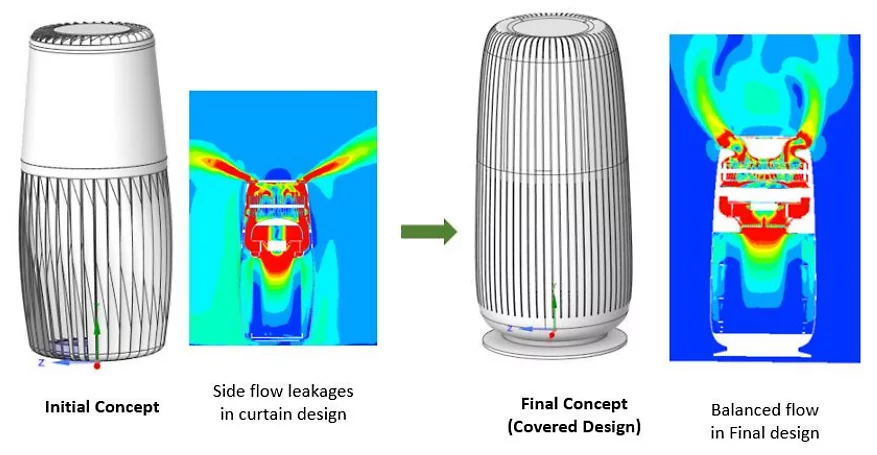
In the initial design of the outer casing (see figure 1), the simulation showed that some of the air escaped out of the sides of the purifier unit, before reaching the top catalytic purifier unit. This meant that some particulates and VOCs were passing into the ambient atmosphere, to be breathed in by anyone in the room. Part of this was due to the thickness of the filter itself.
In the covered design, the HEPA filter — the cylindrical-shaped blue element at the bottom of the simulation images — was made thicker at the bottom and sides. In combination with the new casing design, the simulations showed that all airflow remained inside the purifier, exiting from the jets at the top after all purification had been completed.
Blower Design
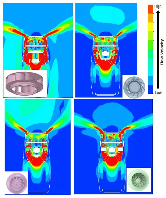
The design of the blower directly affects the flow field, power requirements, and noise level of the purifier. It also determines the velocity and location of the airflow through the TiO2 catalytic and UV purifier above the blower. Ideally, the blower should provide a flow through the center part of the TiO2 module at the highest velocity possible while still leaving enough time for the catalyst to break down the VOCs.
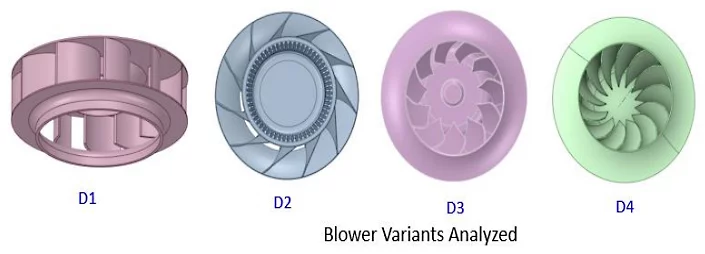
Havells engineers looked at four blower designs (see figure 2) and the flow patterns they caused through the purifier using Fluent. While design D2 originally showed the best flow pattern and velocity for delivering the air to the catalytic module, it was too noisy.